An h-bridge can be used to control a DC motor with a microcontroller like the Arduino Uno. This post discusses how to control a motor using an h-bridge with FlashForth, a Forth for microcontrollers. Controlling an h-bridge with FlashForth is a great way to demonstrate the power interactive programming with the Forth programming language.
Essential Reading
In the spirit of Forth, FlashForth makes no assumptions about which microcontroller it will run on and offers fewer abstractions. Certain things like hardware addresses for I/O pins or how to write pulse width modulation (PWM) signals to a pin will feel a little nebulous. I found these articles to be helpful and suggest you read them as well. The concepts and code shown in this post borrow heavily from these articles.
- Understanding the connectors of Arduino boards: This link discusses how to translate the physical pins, like pin 13, on an Arduino into the binary or hexidecimal bit mask values. This is important for understanding how the port addresses shown in this post are derived.
- Control an LED by PWM in 176 bytes: This link discusses how to use pulse width modulation on the Ardunio Mega to control the brightness of an LED.
- defPin: An implementation of the
defPin:word. - L239D H-Bridge Datasheet
- Aquaticus PWM Guide
Disclaimer
FlashForth is licensed under GPLv3 and the examples in this article are derived from GPLv3 licensed code. Therefore, all code in this article is licensed under GPLv3 as well. Additionally, this article contains links to affiliate sites. If you buy something by following one of these links, I make money.
Bill of Materials
- Arduino Uno (With FlashForth installed)
- L239D H-Bridge
- A DC Motor
- Jumper Wires
- Breadboard
- 9v Battery
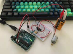
The Board
Before you begin, be sure to review the L239D H-Bridge Datasheet. Page 3 shows the pin layout of the integrated circuit. The circuit configuration for this demonstration uses a nine volt battery to power the motor while the Arduino controls the amount of power sent from the battery to the motor as well as the direction of the motor.
- Orient the Arduino Uno so the USB port faces away from you. Place the breadboard on the right-hand side of the Arduino next to the digital pins.
- The L239D h-bridge has small
Ushaped dimple. Orient the h-bridge so theUshape is facing the same direction as the USB port on the Arduino Uno and place it in the middle of the breadboard so it straddles the groove in the center of the breadboard. - Connect the top left pin (1,2EN) of the L239D to pin 9 on the Arduino. Pin 9 on the Arduino will use the PWM duty cycle on the Arduino to control the motor speed via the enable pin of the L239D h-bridge (1,2EN = ENable channel 1, channel 2).
- Connect the second top left pin of the h-bridge (1A) to pin 7 of the Arduino. This is the first control pin use to control the direction of the motor.
- Connect the third top left pin (1Y) of the h-bridge to the negative lead of the motor.
- Connect the forth (4) and fifth (5) pins of the h-bridge to the ground bus of the breadboard.
- Connect the sixth pin (2Y) of the hbridge to the positive lead of the motor.
- Connect the seventh pin (2A) of the bridge to pin 4 of the Arduino. This is the second control pin used to control the direction of the motor.
- Connect the eighth pin (Vcc2) to the positive bus on the right hand side of the breadboard.
- Connect the top right pin (Vcc1) to the positive bus on the left hand side of the breadboard.
- Connect Arduino
GNDpin to the left hand breadboard negative bus. - Connect Arduino
5vto the right hand breadboard positive bus. - Connect the nine volt battery positive lead to the right hand positive bus.
- Connect the nine volt battery negative lead to the left hand negative bus.
The Code
Make Your Mark
No, seriously, use a marker. In Forth “words” (commands or functions in other languages) live in the dictionary. The dictionary is a linked list where one word points to the previously defined word and the next word. Deleting a word means splicing and reattaching the list like two pieces of film. In most Forth implementations the word forget serves this role. FlashForth does not include forget by default, but it is possible to extend FlashForth by including forget. However, forget is not without downsides. In particular, you must forget every word you wish to redefine. A marker on the other hand will erase all words that have been defined after the marker was set. Much more convenient when iterating on a problem and the machine needs to be in a known state. One thing to be aware of when using markers is that if code is split over multiple files all files must be reloaded in order because a maker will erase all words defined after the marker including words that are defined after another marker defined after the original marker.
-hbridge

marker -hbridge
Debugging Tip: If you change your maker and suddenly your code is not working double check the dictionary by typing words to confirm you deleted the old marker. If you did not delete the old maker, type it and press enter to delete the words associated with that maker.
Some Helpful Helpers
aduino-forth.com is a great place to start as a reference for using Forth on the Arduino. These helpers are borrowed from this site.
: defpin:
  create
    c, c,
  does>
    dup c@
    swap 1+ c@
;
defpin: is a handy word for assigning a port and pin bitmask to a Forth constant (constants are also words).
: high mset ;
: low mclr ;
high and low are used to control the high bit or low bit of a pin.
: output 1- high ;
: input 1- low ;
output and input control whether or not a digital pin is writing out or reading in. If a pin is set to output and high the pen is writing (sending voltage). In other words, the in is “on“.
Register the Registers
\ Digital I/O Registers
36 constant ddrb
37 constant portb
41 constant pind
42 constant ddrd
43 constant portd
\ PWM Registers
128 constant tccr1a
129 constant tccr1b
134 constant icr1
136 constant ocr1a
These registers are uses to control the state of the motor direction and as well as the clock used to control the PWM. ddr* meands data direction register. ddrb has a relationship to pinb. Data direction registers and pin registers are used to control whether or not a pin is configured to read or write. Take a look at this reference to see where the decimal values for these registers are obtained.
Define the Pins
\ Set the memory context to flash to persist
\ pin definitions between restarts
flash
portd $0080 defpin: ctl1 \ bit7
portd $0010 defpin: ctl2 \ bit4
portb %00000010 defpin: enable \ bit1/oc1a
\ Return memory context to ram
ram
Here is where we get to use the handy helpers to define our digital I/O pins. ctl1 is pin 7 on the Arduino, which represents bit 7 of port D on the ATMega328. ctl2 is bit 4 of port D. Note that we are setting the memory context to flash before defining the pins. This is done to allow the pin definitions to persist between restarts of the device. If the pins are defined in ram the words for the pins will still be present in the dictionary however the values are lost. This results in a very unobvious bug where everything appears to be correctly defined but it isn’t apparent that the values of the pins have been lost.
Initialize the Ports
: init.ports ( --- )
  ctl1 output
  ctl2 output
  enable output
  %10100000 tccr1a c!
  %00010010 tccr1b c!
  $4e20 icr1 !
;
ctl1, ctl2, and enable are used to control the h-bridge. tccr1a, tccr1b, and icr1 are used to control the PWM cycle.
Power to the… Motor
: power ( n - ) ocr1a ! ;
The power word allows us to write a “power” value to the ocr1a register which will control the pulse width modulation cycle. This word expects a 16 bit integer to be on the stack. For example 10000 power.
Control the Motor
: c-clockwise ( --- )
  ctl1 high
  ctl2 low
;

: clockwise ( --- )
  ctl1 low
  ctl2 high
;

: stop ( --- )
  ctl1 low
  ctl2 low
;
These words control the whether or not the motor is moving and what direction the motor moves. Their purpose is obvious. c-clockwise turns the motor counter clockwise by manipulating the ctl1 and ctl2 pins which control the polarity of the h-bridge pins they are connected to. clockwise turns the motor clockwise by reversing the pin outputs. stop stops the motor from turning by disabling both control pins.
View the complete listing of the code here.
Interactive Development
Previously I wrote about interactive development using GNU screen. Screen works well enough but there are a few drawbacks that make it unappealing. The main gripe I have with using screen is that pasting code doesn’t work very well. I had to use the iTerm paste slower option to allow pasting code into a screen session at a rate that the Arduino can handle. Lately I have been using cu for interactive development instead. Loading files with cu works much better. In cu you enter ~> and press enter. A file prompt displays and you can enter the path to the file you want to load. cu handles sending the file at the correct baud rate. The only downside to uploading a file with cu is that you won’t see compiler errors from FlashForth as the file is processed. If you make a mistake it can be more difficult to determine the source.
To connect to a device with cu you provide the baud rate and the device path just like screen.
cu -l /dev/tty.usbmodem142401 -s 38400
You should see something like this.
Connected.
E FlashForth 5 ATmega328 13.01.2019
Let’s say we have all the code above in a file called hbridge.fs that we want to upload. In the cu terminal session enter this symbol.
~>
Press enter and you will see a file upload prompt.
File to send:
Type the name of the file to upload, in this case, hbridge.fs, and press enter.
File to send: hbridge.fs
There will be a progress reading as the file is uploaded and finally a message saying the file transfer is complete.
1 2 3 4 5 6 7 8 9 10 11 12 13 14 15 16 17 18 19 20 21 22 23 24 25 26 27 28 29 30 31 32 33 34 35 36 37 38 39 40 41 42 43 44 45 46 47 48 49 50 51 52 53 54 55 56 57 58
[file transfer complete]
After the file uploads, press enter one or two times more until you see ok<#,ram>. Now type words. Our newly defined words from hbridge.fs are now present in the dictionary. Lets take them for a test drive.
First, initialize the ports.
init.ports
Next, set a power level. This tells the h-bridge how much power to send to the motor.
10000 power
Now turn the motor on.
clockwise
The motor will jump to life. As it spins you can increase or decrease the speed by sending a new value to power. The power word accepts any 16 bit signed integer. Try typing 5000 power.
Change the motor direction.
c-clockwise
Stop the motor.
stop
This example demonstrates the power of interactive development with Forth. Forth allows you to exercise every word individually without recompiling your code.
Troubleshooting
A useful troubleshooting technique is to set up an LED with some jumper wires and a resistor that can be used to determine if your pins are sending voltage. For example, let’s say we typed 100 power and the motor didn’t work. We can determine if our code is behaving correct but 100 power is not enough to turn the motor. We can use the same technique to determine if power is being sent to ctl1 or ctl2.
Another useful troubleshooting technique is the call the individual words defined for pins to verify their values are correct. For example if defpin: is called when the memory context is set to ram the pin definitions are lost if the device loses power or is reset.
Pins defined in ram and lost due to reset.
ctl1 ok<#,ram> 0 0
Pins defined in flash and persist during reset or power loss.
ctl1 ok<#,ram> 128 43
This issue usually becomes obvious when a reset or power loss occurs and functionality is restored after re-loading a file, which clears the dictionary up to the marker and redefines everything set after the marker, resetting the values of the pins in the process. If you observe this behavior, try inspecting the values of the words defined to control ports or registers by calling them in the interpreter.
Conclusion
It took quite a bit of iteration on my part to produce a working example. I really could not have done it without the resources available on arduino-forth.com. Forth is challenging to work with by virtue of not being as popular as languages like C or C++. Investing the time to develop an in depth understanding of the hardware is required. A missing piece of the puzzle is a comprehensive overview of how to control the various features of the ATMega328p with FlashForth (or any Forth). It would be wonderful to have a book that dissects the hardware using Forth as the scalpel while providing reference tables to the decimal, hex, and binary values for the various ports, registers, and settings on the ATMega328p.
Despite the challenges to using Forth on this hardware I feel Forth is well suited for the task. The ability to test commands individually and interactively simplifies the task of creating the necessary abstractions to control a complex piece of hardware in an environment where ready-made answers are uncommon. I hope practical examples such is this post and the articles on arduino-forth.com will enable others to experiment with FlashForth on the Arduino.